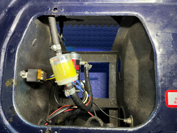
Cost effective Cooling fan control
Automating the system: In March 2020 we faced our first lockdown. Looking for things to keep me occupied I decide to look into automating the MGB electric cooling fan. Having an electronics background, I thought I could build a simple temperature controller based around an NTC Thermistor, the industrial staple used in most commercial/industrial temperature control processes. (Air con, Fridges, etc.)
(NTC thermistors are semiconductor resistors that exhibit a negative temperature coefficient, meaning their resistance decreases as the temperature rises. with an accuracy of 0.1 °C. It was whilst looking for one of these that I came across a ready built controller on a well-Known auction site. (W1209 12V Digital Temperature Controller Switch Relay + Sensor Temp Thermostat)
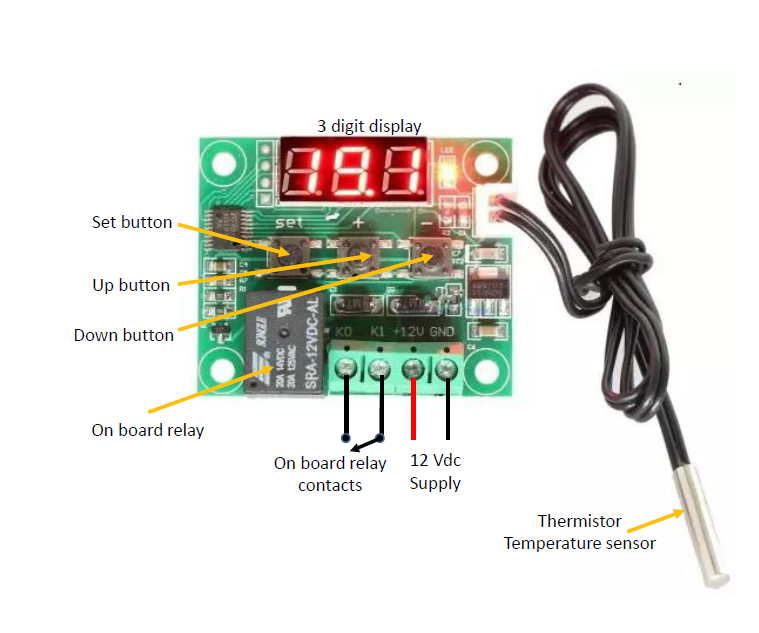
The price was around £ 2.80 in 2020 including the thermistor (Now around £ 4.50) so I ordered 2. What did I have to lose! These arrived a week or so later complete with lost in translation Chinese instructions. So, first job was trying to understand the unit’s operation. The controller was approx.50mm x 40 mm x 20mm, had a 3-digit display and 3 buttons, Set, Up and Down to set the operating temperature and programming parameters. It also had an onboard relay. There was a 4-way connector block for +/-12 volt and the switched onboard relay contacts.
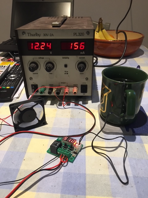
Using a 12 V lab power supply, a small lap top fan and heat source (Cup of coffee) I assembled the bits on the kitchen table and set about working out how it operated. In reality it was very easy.
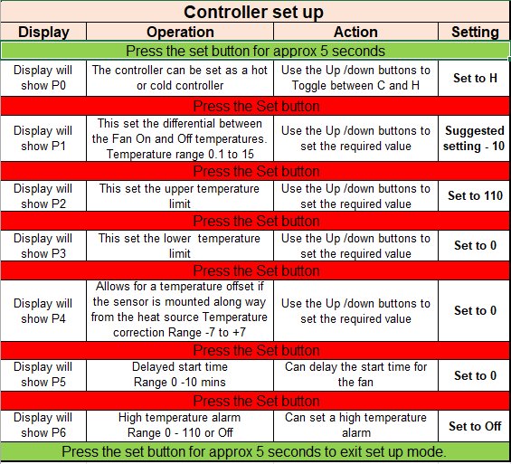
Setting up the controller: To use the controller it first needs to be programmed. This only has to be done once as the parameters are saved even when disconnected from the power. This can be done once installed in the car and only takes a couple of minutes.
Installing the controller
Temperature sensor: This needs to be attached to the radiator. The thermistor temperature sensor is approx.25mm x 4mm diameter. It fits perfectly into the metal part of a single female bullet connector. (Black insulation removed). The radiator needs to be drained, a small area of metalwork of the radiator header tank, on the left-hand side (Looking into the engine compartment.) needs to be cleaned up. Using a large soldering iron soft solder, the metal part of the bullet connector to the radiator. Make sure you have the joint in the connector facing outwards. This can be done with the radiator in situ but it would be easier to do with the radiator removed. When cool paint the area with black paint to tidy up. The sensor can now be pushed into place.
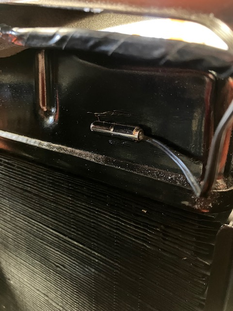
Run the wire from the thermistor with the existing fan wiring round the inner wing back to the controller. It is fitted with a plug to connect to the controller.
Mounting the controller: Electronics and the harsh environment of an engine compartment do not mix well. So, it is important to mount the controller well away from any adverse heat sources. I bought a small ABS plastic box (63.5 X 43.5 X 25mm) to house the controller. This will slide very conveniently into the gap between the inner wing and the fuse mounting panel making it easy to access and away from heat. Mounting the controller in this position also helps keeps the wiring to a minimum.
Wiring the controller: The controller is fitted with a 4-way connector with the wire connections facing outward. To enable the controller to fit and be wired up I de-soldered the connector and reversed it so the wires connectors faced inwards. Alternatively, you could buy a bigger box to accommodate the controller as it is.
The 4-way connector block provides +/-12 volt for the controller and the switched onboard relay contacts that can be wired in parallel across the manual override switch. In reality you only need 3 wire, +/-12 volt and a wire from the onboard relay contact to the override switch. The other relay connection can be linked from either the Plus or minus of the 12v power wires, depending on your car’s polarity.
In operation: Once wired up and the temperature sensor plugged into the controller, turn on the ignition switch. The controller will power up in normal operating mode. Follow the instruction in the above table to set up the controller. This is only need to be done once as the parameters will be saved. Don’t worry if the controller exits the Programming mode (Automatic after 5 seconds if no button pressing is detected) as you can edit any of the values at any time later.
Once the programming is finished it is time to set the on temperature for the fan. Momentarily press the Set button causing the display to flash. Use the Up/Down button to set the Fan ON temperature. In use I have found 99° C work well. This means the fan will start to operate when the radiator temperature reached 99 Degrees. With the differential temperature set to 10 (see P1 in Programming table) the Fan will now run until the radiator temperature drops back to 89° C. (99 – 10 =89). The controller is now set ready for use. Start the car and allow the engine to warm up while observing the display on the controller. Check the fan turns ON and OFF at the set temperatures.
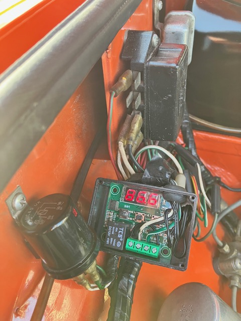
Fit the lid on the plastic box and tuck away between the wing and fuse holder bracket.
Footnote: The controller has been fitted to my car now for 5 years and has performed perfectly over this time. I recently bought a new controller to fit to my son in laws MK1.5 E type Jag. The manufactures have changed the ON temperature setting. This is now the OFF temperature. The ON temperature will now be the OFF Temperature plus the Differential setting in P1. Using the above example, the On Temperature will need to be set to 89° C. (89 +10 =99.)
Mike Barclay